Full-screen 3D Viewer in Envision Viewer
The full-screen 3D viewer empowers you to view and navigate a 3D model and to select and hide parts on the full screen of the Canvas Envision Viewer. When you run the full-screen 3D viewer, you exit the 2D document page view and enter the 3D model viewer, which occupies the entire screen of the Canvas Envision Viewer and has a different screen composition. The full-screen 3D viewer shows only the model from all the page objects and includes features for viewing manipulations of the model and parts. To return to the 2D document page view, you should quit the full-screen 3D viewer.
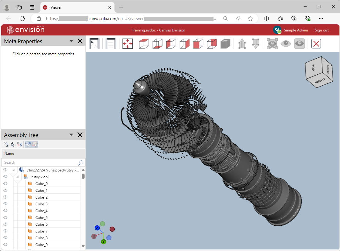
In the full-screen 3D viewer, you can manipulate the 3D model as follows:
Starting the full-screen 3D viewer in the Envision Viewer
To start viewing a 3D model on the full-screen of the 3D viewer in the Envision Viewer:
Hover over the 3D model object. The dotted red object bounding box appears.
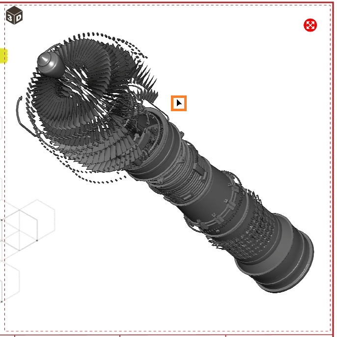
Click the View 3D Model Full Screen round red button in the top right corner of the 3D model object's bounding box.

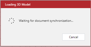
The Loading 3D Model dialog pops up and displays the progress of loading the model.
Once the model is loaded, the Loading 3D Model dialog disappears, and the full-screen 3D viewer screen replaces the Canvas Envision Viewer's toolbar and canvas. The on-page 3D viewer displays only the 3D model from the page contents and includes features for viewing manipulations of the model and parts.
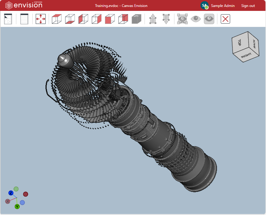
Screen composition of the full-screen 3D viewer
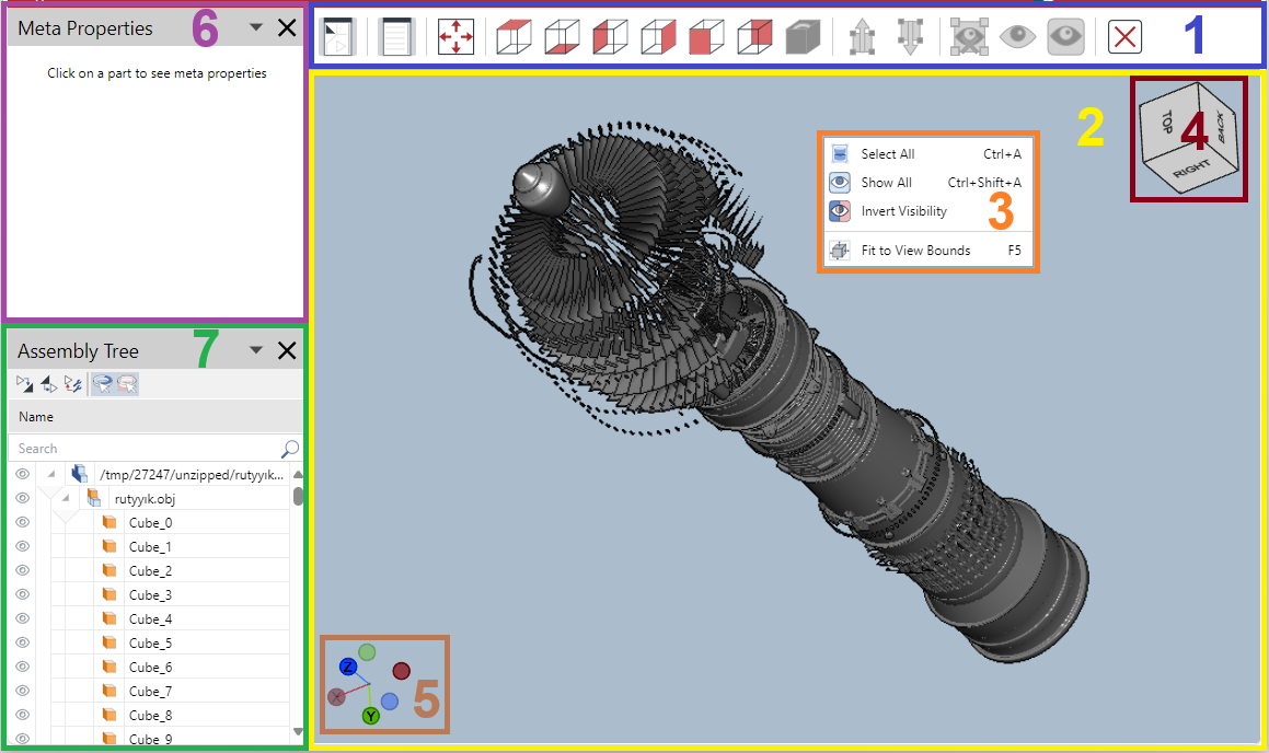
The full-screen 3D viewer's screen includes the following:
Toolbar: the buttons for rotating the camera, selecting, and hiding parts.
Viewport: the scene of the 3D model that you manipulate for viewing.
3D Context-sensitive menu: the commands for selecting and hiding parts.
Navigation cube: a control to rotate the camera to the preset directions by double-clicking on the cube or freely dragging it around.
Axis triad: a control to rotate the camera to the preset directions by double-clicking on the triad (X, Y, Z) or freely dragging it around.
Meta Properties pane: the meta properties of a selected part.
Assembly Tree pane: the hierarchical assembly structure of the 3D model parts. Here, you can explore, search, select, deselect, hide, and show parts.
Toolbar of the full-screen 3D viewer

The full-screen 3D viewer's screen toolbar includes the following buttons for rotating the camera, selecting, and hiding parts:
Assembly Tree: to show or hide the Assembly Tree pane.
Meta Properties: to show or hide the Meta Properties pane.
Fit to Screen: to zoom the camera so that the 3D model or selected parts fit the 3D model object bounding box.
View Top: to rotate the camera to the top face of the 3D model or selected parts.
View Bottom: to rotate the camera to the bottom face of the 3D model or selected parts.
View Left: to rotate the camera to the left face of the 3D model or selected parts.
View Right: to rotate the camera to the right face of the 3D model or selected parts.
View Front: to rotate the camera to the front face of the 3D model or selected parts.
View Back: to rotate the camera to the back face of the 3D model or selected parts.
Reset View: to restore the default zoom and position of the 3D model or selected parts.
Select Tree Up: to select all the parts up the assembly tree from the selected part.
Select Tree Down: to select all the parts down the assembly tree from the selected part.
Hide Selection: to hide the selected parts.
Isolate: to keep the selected parts visible, zoom them to fit the screen, and hide all other parts.
Show All: to show all the hidden parts.
Exit: to stop viewing a 3D model in the full-screen 3D viewer, quit this viewer, and return to the regular 2D view of the page.
Context-sensitive menu of the full-screen 3D viewer
In the full-screen 3D viewer, the context-sensitive menu includes the selection and visibility control commands for a given 3D model and selected parts.
The content of the menu commands is different in the following cases:
No parts are selected.
At least one part is selected.
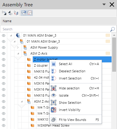
On the full-screen 3D viewer's screen, the context-sensitive menu is available at the Viewport and Assembly Tree pane.
Full-screen 3D viewer's context-sensitive menu when no parts are selected
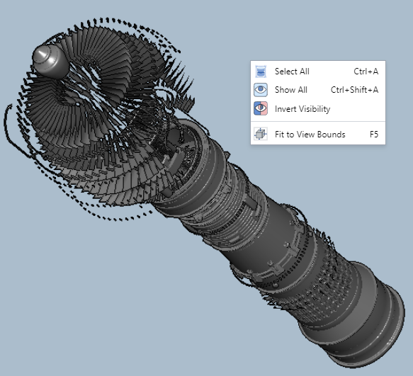
When no parts are selected on the 3D model, the context-sensitive menu has the following commands:
Select All: to select all the parts.
Show All: to show all the hidden parts.
Invert Visibility: to hide all the visible parts and show all the hidden parts.
Fit to View Bounds: to zoom the camera so that the 3D model or selected parts fit the 3D model object bounding box.
Full-screen 3D viewer's context-sensitive menu when one or more parts are selected
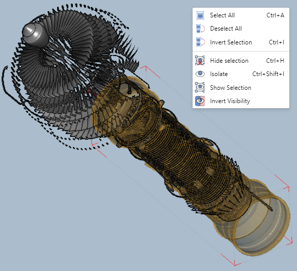
When one or more than one part is selected on the 3D model, the context-sensitive menu has the following commands:
Select All: to select all the parts.
Deselect All: to deselect all the parts.
Invert Selection: to select all the unselected parts and deselect all the selected parts.
Hide Selection: to hide the selected parts.
Isolate: to keep the selected parts visible, zoom them to fit the screen, and hide all other parts.
Show Selection: to show the selected hidden parts.
Invert Visibility: to hide all the visible parts and show all the hidden parts.
Accessing the general context-sensitive menu on the full-screen 3D viewer's screen
To access the general context-sensitive menu:
Ensure no part is selected.
Right-click anywhere in the viewport.
Accessing the part context-sensitive menu on the full-screen 3D viewer's screen
To access the context-sensitive menu for one or more parts:
Select one or more parts in the viewport or the Assembly Tree pane.
Right-click anywhere in the viewport or on the selected parts in the Assembly Tree pane.
Meta Properties pane of the full-screen 3D viewer
- Meta-properties
Custom properties or attributes that model creators add to 3D parts and assemblies with 3D CAD authoring tools to provide additional information about these parts and assemblies.
Some examples of common meta-properties are the following:
Part number
Revision number
Description
Material
Manufacturer
Weight
The Meta Properties pane displays the meta-properties of a selected part if it has any.
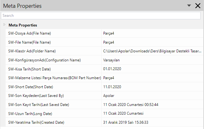
Showing and hiding the Meta Properties pane in the full-screen 3D viewer
By default, the Meta Properties pane is hidden on the first opening of the full-screen 3D viewer for a given document. Once the pane is shown, it will be visible and present at the same location on further document openings.
To show or hide the Meta Properties pane:
Click the Meta Properties button on the full-screen 3D viewer's screen toolbar.

Viewing meta-properties in the full-screen 3D viewer
To view the meta-properties of a part:
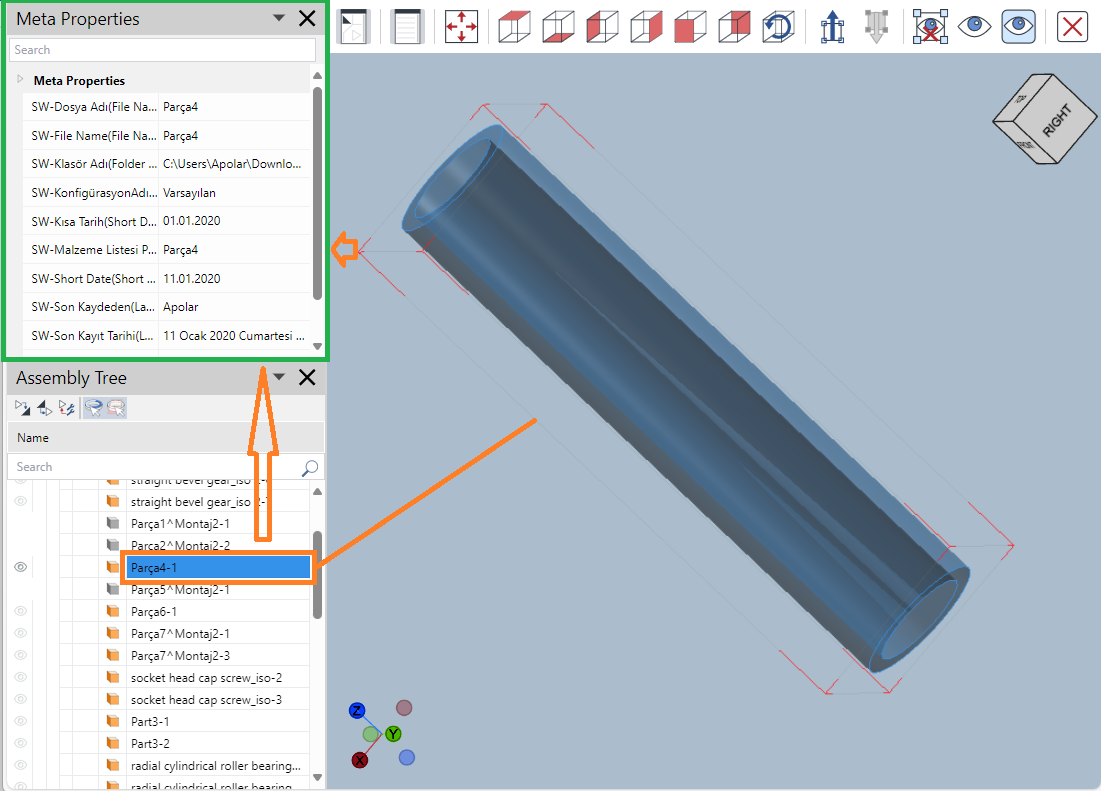
Select the part in the viewport or the Assembly Tree pane.
Open or go to the Meta Properties pane.
If the selected part has meta-properties, the pane displays these properties.
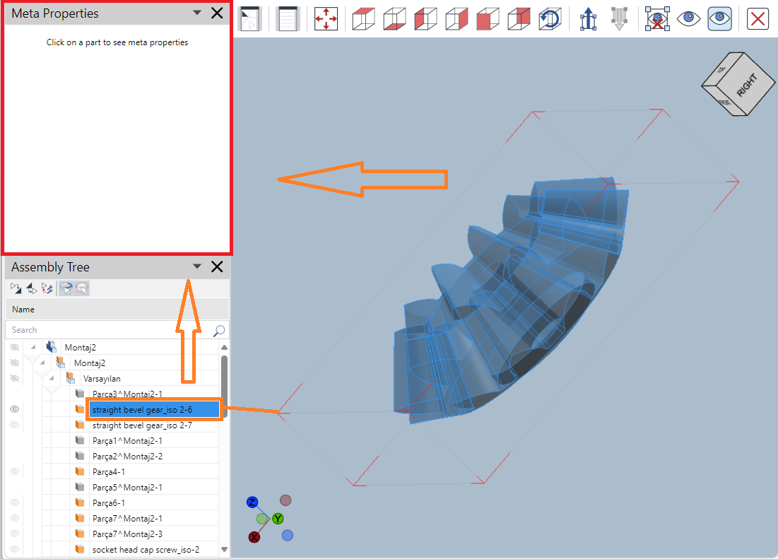
If the selected part has no meta-properties, the pane is blank.
Assembly Tree pane of the full-screen 3D viewer
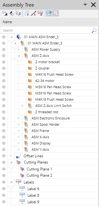
The Assembly Tree pane displays the parts from a given 3D model recursively from top to bottom in a hierarchical assembly tree, where the assembly root is the 3D model. After the assembly tree, the pane shows the cutting planes, offset lines, and labels attached to the model and parts. It also provides features for exploring, selecting, hiding, and showing the included items.
Showing and hiding the Assembly Tree pane in the full-screen 3D viewer
By default, the Assembly Tree pane is hidden on the first opening of the full-screen 3D viewer for a given document. Once the pane is shown, it will be visible and present at the same location on further document openings.
To show or hide the Assembly Tree pane:
Click the Assembly Tree button on the full-screen 3D viewer's screen toolbar.

Composition of the Assembly Tree pane of the full-screen 3D viewer
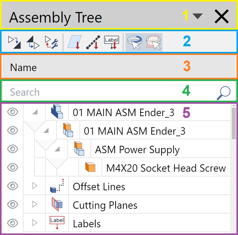
The Assembly Tree pane of the full-screen 3D viewer includes the following:
The title bar that provides the features to reposition and hide the pane.
The toolbar that provides the features to manage the assembly tree and item selection.
The Name button to sort the assembly tree against the item name in ascending or descending order.
The Search field to filter out the assembly tree against the typed search criteria.
The assembly tree grid that displays the parts, offset lines, cutting planes, and labels from the 3D model recursively.
Toolbar of the Assembly Tree pane of the full-screen 3D viewer

The toolbar of the Assembly Tree pane of the full-screen 3D viewer includes the following buttons:
Expand All: to expand all assemblies, subassemblies, and groups in the tree.
Collapse All: to collapse all assemblies, subassemblies, and groups in the tree.
Collapse Lower Levels: to collapse all subassemblies and groups at a given tree level.
Go to cutting planes: to quickly scroll the tree down to the Сutting Planes group in the tree.
Go to offset lines: to quickly scroll the tree down to the Offset Lines group in the tree.
Go to labels: to quickly scroll the tree down to the Labels group in the tree.
Select parts: to allow part selection in the viewport if it is selected. You can select the parts only in the Assembly Tree pane if it is not selected. It is selected by default.
Select Collaboration: to allow cutting plane and offset line selection in the viewport if it is selected. You can select the cutting planes and offset lines only in the Assembly Tree pane if it is not selected. It is selected by default.
The Go to cutting planes, Go to offset lines, and Go to labels buttons are dynamically included. The pane toolbar has the button only when the pertinent items exist in the assembly tree. For example, the Go to cutting planes will not be on the toolbar if the 3D model has no cutting planes.
Assembly tree grid in the Assembly Tree pane of the full-screen 3D viewer
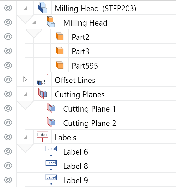
The Assembly Tree pane uses a grid to show the following items included in the 3D model:
Subassemblies (components)
Parts (end or leaf parts)
Non-visual items
Offset lines
Cutting planes
Labels
Assembly tree grid rows
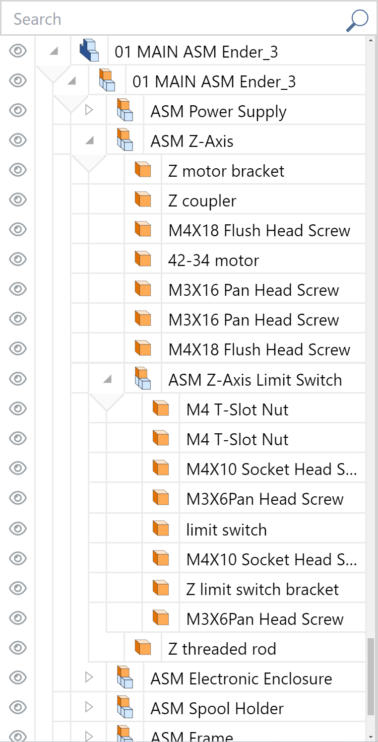
Each item included in the 3D model is a row in the grid. By default, the first row is the apex level of the assembly tree—the assembly root that represents the 3D model. Subassemblies, parts, and non-visual items are displayed as a recursive tree of rows from the assembly root to the bottom. The assembly root can include one or more subassemblies and parts. Each subassembly creates a branch of one or more subassemblies and parts. Those subassemblies create their branches, and so on: the process drills the tree down to the end parts in each branch.
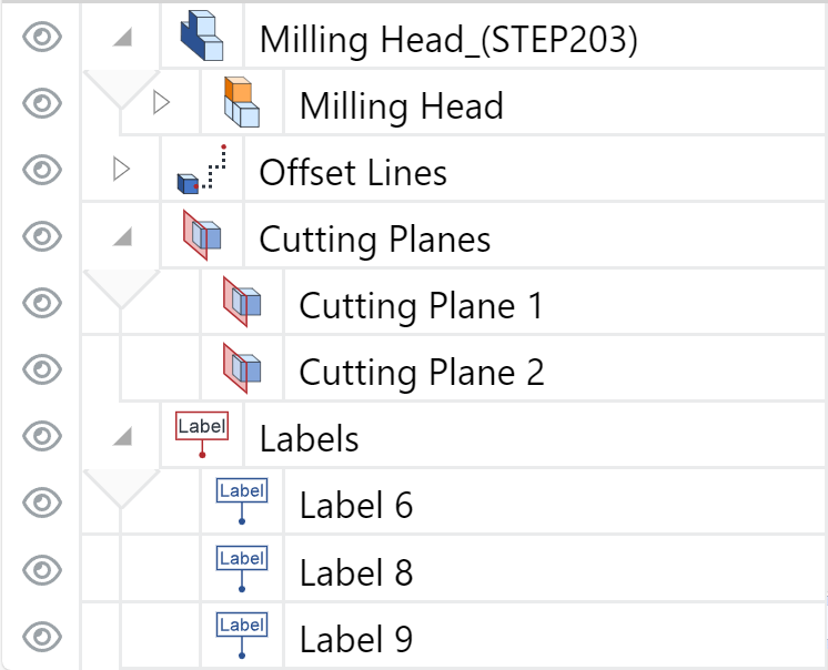
After the assembly tree, the grid displays the offset lines, cutting planes, and labels attached to the model and parts. Each kind is gathered into a group represented by a separate top-level row:
Offset Lines
Cutting Planes
Labels
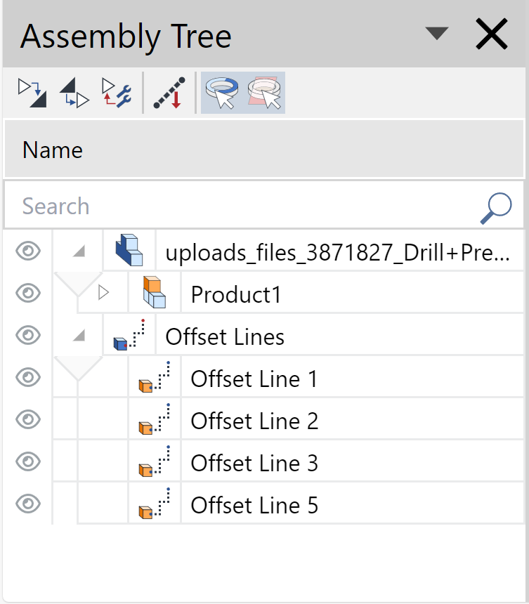
The Offset Lines, Cutting Planes, and Labels groups are dynamic: the grid displays only the groups of items included in the model, and the pane toolbar includes the quick-access buttons only for the displayed groups. For example, if the model has none of such items, all the groups will not be in the grid, and the Go to cutting planes, Go to offset lines, and Go to labels buttons will not be on the toolbar. If the model has offset lines, only this group will be in the grid, and only Go to offset lines from the buttons in question will be on the toolbar.
Assembly tree grid columns
The grid columns provide tools and visual clues for exploring and understanding the grid contents.
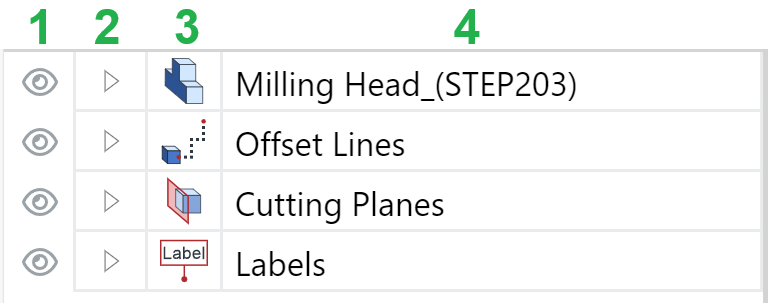
The Assembly Tree pane grid has the following columns:
Visibility
Tree Level
Type
Name
Visibility column of the Assembly tree grid
The Visibility column includes a button with an eye icon. Clicking the button toggles the visibility of a given item in the viewport. You can hide or show parts, subassemblies, assemblies, cutting planes, offset lines, labels, and their groups on the 3D model in the viewport. Clicking a subassembly, assembly, or group hides or shows all the included parts or items. The eye icon displays the item's visibility status as follows:

Clear and dark
The item is shown, or all items included in the assembly, subassembly, or group are shown.
Clicking the button hides the item or all items in the assembly, subassembly, or group.

Faded
The item is hidden, or all items included in this assembly, subassembly, or group are hidden.
Clicking the button shows the item or all items in the assembly, subassembly, or group.

Slashed and faded
Some items in this assembly, subassembly, or group are hidden.
Clicking the button shows the hidden items in the assembly, subassembly, or group.
Tree Level column of the Assembly tree grid
The Tree Level column displays where on the tree or group a given item is with the help of vertical lines. There is a vertical line for each tree level. The left-most vertical line goes down from the apex level. A lower level has a line on the right of the upper level's line. To understand an item's level, you should track the bottom line of its row in the right-to-left direction from the Type column. The intersection of the right-most vertical line in the Tree Level column and the bottom line of the item's row indicates the item's level.
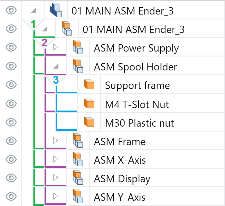
The Tree Level column is dynamic. For each level, it includes an Accordion button to expand and collapse the level. The visibility of the level rows defines the button look and behavior on clicking as follows:

Expanded
The button is a filled-in gray triangle pointing to the bottom right corner of the cell, which has light gray borders for all sides except the bottom. The cell bottom has no border but has an attached gray triangle pointing down. From the triangle's lower angle, a vertical line goes down to denote a given level.
Clicking the button collapses the level.

Collapsed
The button is a white triangle with gray borders pointing to the right of the cell, which has all the borders light gray.
Clicking the button expands the level.
Type column of the Assembly tree grid
The Type column displays icons that identify items as follows:

Assembly root

Subassembly

Part

Ghosted part or subassembly

Non-visual item

Group of offset lines

Offset line

Group of cutting planes or cutting plane

Group of labels

Label
Name column of the Assembly tree grid
The Name column displays the names of the items. Additionally, it provides a visual clue about the branch of a selected part or item. A golden rectangle icon on the right side of a Name cell tells that the selected part or item belongs to this assembly, subassembly, or group. Each parent on the branch has this icon.
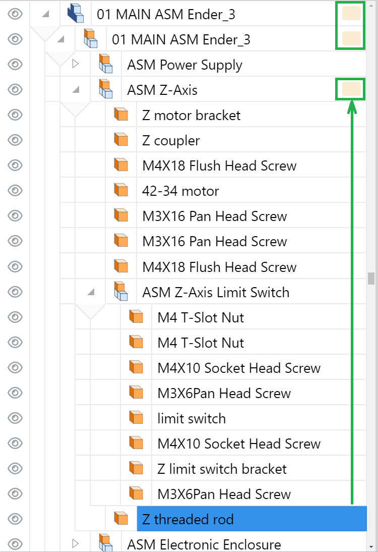
Managing the panes in the full-screen 3D viewer
On the full-screen 3D viewer's screen, you can manage the Meta Properties and Assembly Tree panes as follows:
Rearrange their position.
Resize them.
Rearranging panes on the full-screen 3D viewer's screen
On the first opening of the document, the Meta Properties and Assembly Tree panes are docked to the left side of the viewport by default.
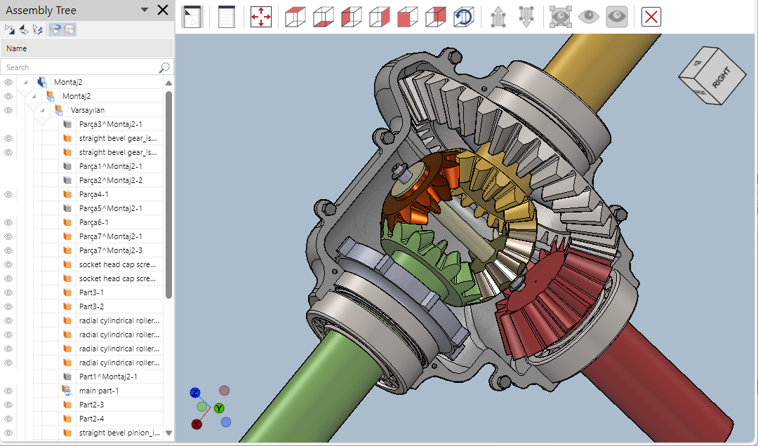
You can rearrange this default position by docking the panes to the left and right as you wish.
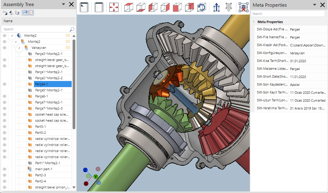
When both panes are docked on one side, one is at the top, and another is at the bottom. In such a case, you can toggle their position on the side.
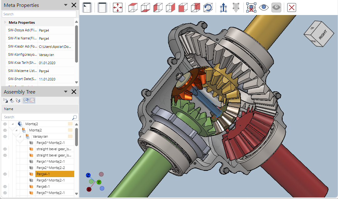
To rearrange the position of the pane:
Click the menu button on the right of the pane title bar.
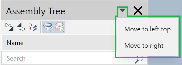
The menu drops down and displays the currently available rearrangement options.
Click the option where you want to move the pane. The pane is moved.
Resizing panes on the full-screen 3D viewer's screen
You can update the width of the pane docked to the left or right. When both panes are docked to one side, you can update their heights.
Changing pane width
To change the width of the pane docked to the left or right side of the viewport:
Hover the cursor on the line between the pane and the viewport until the cursor becomes a horizontal double-headed white arrow.

Click and drag left or right. The system updates the widths of the pane and viewport in response to your dragging.
Changing pane heights
To change the heights of both panes when they are docked to one side:
Hover the cursor on the horizontal line between the panes (the top line of the lower pane's title bar) until the cursor becomes a vertical double-headed white arrow.
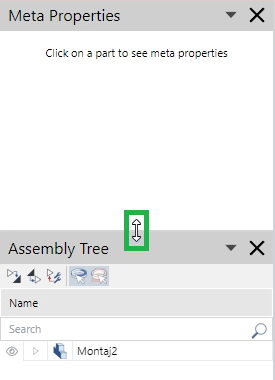
Click and drag up or down. The system updates the heights of both panes in response to your dragging.
Quitting the full-screen 3D viewer in the Envision Viewer
To stop viewing a 3D model in the full-screen 3D viewer, quit this viewer, and return to the regular 2D view of the page:
Click the Exit button on the full-screen 3D viewer's screen toolbar.
