Creating Vector Objects from Images
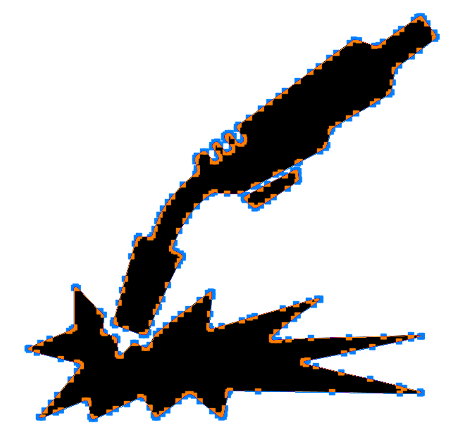
You can create vector objects from an image with the Auto Trace command. It works especially well with high-contrast images, such as a silhouette in black and white or a posterized image of several colors.
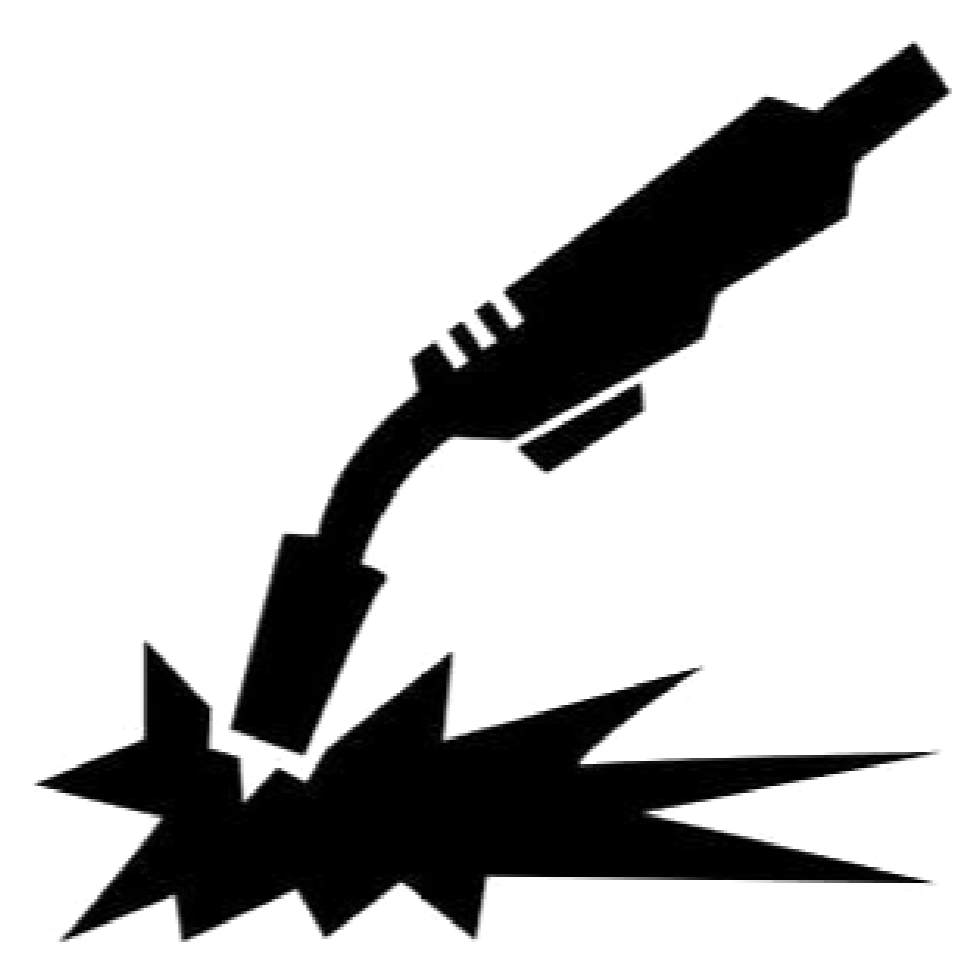
High-contrast silhouette image
High-contrast silhouette image
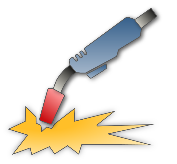
Objects after vector editing


Auto-tracing is much faster than manually tracing an image with the drawing tools like the Polygon or Bézier curve.
Auto Trace works with large high-resolution images better than small low-resolution images. It may require some vector editing to tweak vector paths because of produced jagged paths.
Creating vector objects from an image
To create vector objects from an image:
Select the image from which you want to create vector objects.
Click the Auto Trace button in the Trace panel on the Image contextual ribbon tab.

The Auto Trace dialog box pops up.

Set the trace parameters in the Input and Output sections of the new vector objects in the Auto Trace pop-up dialog box.

From the drop-down list in the bottom left corner of the Auto Trace pop-up dialog box, specify what to show in the Page Layout Area, either:
Show both input & output
Show both input
Show both output
When done, click either:
Apply to check the result. The dialog box remains open.
OK to execute the operation and close the dialog box.
Cancel to void the operation and close the dialog box.
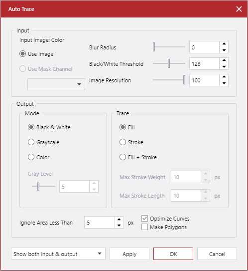
Auto Trace pop-up dialog box
The Auto Trace pop-up dialog box includes the Input and Output sections.

Input section of the Auto Trace pop-up dialog box
The Input section of the Auto Trace pop-up dialog box provides the following configuration options for the image being traced:
Use Mask Channel: depending on the image type, you can select All Channels or a specific color channel from the menu. If the image contains only one color channel, like grayscale or black and white, this radio button and drop-down list are disabled.
Blur Radius: a blur radius to the input image. Blurring removes noise.
Black/White Threshold: this slider is only enabled when the input image is grayscale or color and the output result is black and white. In this case, it modifies the intermediate black & white image used to create the vector (traced) objects.
Image Resolution: this slider adjusts the resolution of the input image. The input image can be traced at its original resolution or at an adjusted one. The Intermediate Preview indicates the image used for tracing after applying the blur or threshold changes, if applicable.
Output section of the Auto Trace pop-up dialog box
The Output section of the Auto Trace pop-up dialog box provides the following configuration options for the vector objects being created:
Mode: the otput of the tracing, either:
Black & White
Grayscale
Color
Gray Level: this slider is only enabled when the output is either:
Grayscale: the level value defines the number of gray levels in the intermediate preview and in resulting vector object.
Color: the slider controls how well the details in the image are distinguished. A high value provides better distinction.
Trace: either:
Fill: creates filled outlines.
Stroke: is only available when the Mode is Black & White. It means that centerlines with an approximate width are created rather than outlines.
Fill + Stroke: a mixture of filled vector objects and strokes is made. Strokes are created depending on the values for Max Stroke Width and Min Stroke Length.
Ignore Area Less Than: this option works as a despeckle filter. If isolated pixels or groups of pixels exist in the input image, they will be ignored, instead of creating vector objects from them.
Optimize Curves: this option reduces the number of points in the curve, without drastically affecting the shape. It is disabled if Make Polygons is enabled.
Make Polygons: this option creates polygons rather than Bézier curves. The Output preview displays a portion of the resulting vector objects.